Technical Data
Dimensions
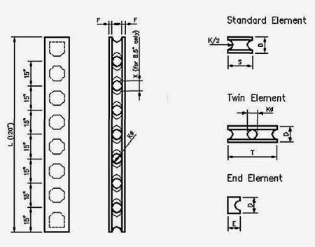
| Thickness | Core Diameter | Flange | Lenght | Single Height | Double Height | End Panel Depth | Core Diameter |
| D | K | F | L | S | T | E | X |
| 6.5”(165) | 4”(102) | 1.25”(32) | 120”(3050) | 15" (380) | 30"(760) | NA | 4,25”(107) |
| 8.5"(215) | 5"(127) | 1.75"(45) | 5.25"(135) | ||||
| 10"(250) | 6"(152) | 2"(50) | 7.5"(190) | NA | |||
| 12"(305) | 6"(152) | 3"(76) | NA | ||||
| 14"(355) | 6"(152) | 4"(100) | NA |
Volumes & Weights
STANDARD/END PANELS
| Thickness | Lenght | Standard Panel -cubic feet (dm³) | End Panel | Weight Std. Panel-lbs (kg) ±10% |
||
| Outside | Cavity | Net | Net | |||
| 6.5”(165) | 120”(3050) | 6.77 (192) | 1.68 (48) | 5.09 (144) | - | 117 (53) |
| 8.5”(215) | 8.85 (250) | 2.63 (74.4) | 6.22 (176) | - | 143 (65) | |
| 10"(250) | 10.42 (294) | 3.67 (104) | 6.75 (190) | 4.22 (119) | 158 (72) | |
| 12"(305) | 12.5 (354) | 8,83 (250) | 5.26 (149) | 197 (90) | ||
| 14"(355) | 14.58 (412) | 10.91 (308) | 6.31 (178) | 243 (110) | ||
| 6.68 (185)* | 7.90 (55) | 5.55 (157) | 175 (79) | |||
Note: 6.5” & 8.5" panels are used for interior non load bearing applications only.
*: 14" thick panels can be ordered with 8" cavities for higher strength requirements.
FLAT PANELS
| Thickness | Width | Lenght | Weight |
| 2" (50) | 30" (760) | 60" (1520) | 50 lbs (22.5 kg) |
| 4” (100) | 100 lbs (45 kg) |
*: may be shipped 3 5/8” thick; **: can be shipped 120” long
General Data
| RASTRA Panel | Concrete Consumption |
| 6½" wide | 0.13 cuft per sqft (41 dm3/m2)of wall surface |
| 8½" wide | 0.21 cuft per sqft (65 dm³/m²)of wall surface |
| 10", 12" & 14" wide | 0.30 cuft per sqft (65 dm³/m²) of wall surface |
| Approximate Weight of Grouted Unfinished Wall | |
| 6½" | 31 lbs per square foot (148 kg/m2) |
| 8½" | 42 lbs per square foot (201 kg/m²) |
| 10" | 57 lbs per square foot (274 kg/m²) |
| 12" | 60 lbs per square foot (288 kg/m²) |
| 14" | 64 lbs per square foot (307 kg/m²) |
| Reinforcement Consumption | |
| 15" centers | 1.17 lineal feet (36m) per square foot of wall surface |
| 30" centers | 0.85 lineal feet (0.25m) per square foot of wall surface |
Physical Properties
| Parameter (report numbers) | Rating/Value | Remarks |
| Recycled Content | ± 85% by volume | Mainly post-industrial expanded polystyrene (EPS). |
| Bulk Density | 22 lbs/ft3 ± 10% | Panels for specific applications may be produced with higher density. |
| Compressive Strength of THASTYRON |
56 psi | Depending on density required. |
| Tensile Strength of THASTYRON | 43 psi | Depending on density required. |
| Water Vapor Transmission PI-4582/ws, 5/80 |
7.3 | This is a (dimensionless) factor to measure possibility of condensation in the wall, particularly in cooler periods or with high air conditioning; the low value of Thastyron is a guarantee that no condensation will occur. |
| Fire Endurance UL – 91NK6768, 9/91, 2/99 BI – 07-106-2147, 10/96 |
4 hour rating (ASTM E119) | A 10" un-plastered RASTRA wall has been tested for 5 hours under a load of 10,000 lbs/lin.ft.; two tests have been performed with an additional positive and negative load perpendicular to the wall, simulating a 35 mph wind pressure; with a temperature in excess of 2000°F on the exposed side the surface temperature on the unexposed side of the wall did not increase for more than 7°F; a high pressure water stream directed towards the wall immediately after burning did not penetrate the wall. |
| Thermal Barrier (Room Fire Test) OPL – 15715-1808, 9/97 |
no flame spread no smoke development wall meets UBC 26-3 |
A wood crib is burned in a corner built with un-plastered RASTRA walls exposing it to 1700°F +/-; flame spread, smoke and any damage of the wall is monitored. |
| Surface Burning Characteristic SGS – 113924. 9/98 |
Flame Spread Index 0 Smoke Development Index 5 NFPA Class A UBC Class 1 ASTM E 84 (NFPA 255, UBC 8-1) |
4" thick Thastyron panels were exposed to flame and spreading of the flame front and smoke density, compared to red oak was measured. The flame front was produced at less than 6", which is within the flame spread of the burner. For smoke development light absorption is measured. The test showed some very low absorption, for the test result values are always rounded to the next figure divisible by 5. |
| Frost Resistance TIB – KR/SI, 10/84 |
Highly Frost Resistant | Thastyron soaked in boiling water and frozen at -4°F; after 50 cycles no reduction of compressive strength could be found. |
| Toxicity BI – 08-95-0338, 5/95 |
Low Toxic | Testing conducted using Leaching Procedure by EPA SW-846 method 1311, metals by method 6010 & 7470, volatiles by method 8240; metals are less than 1/20 of regulatory limit, only traces of 4 volatiles out of 40 tested found. |
| Formation of Mildew API – 17137, 4/83 |
No mildew & fungus growth including black mold | Test cubes were kept under moist conditions for 40 days after inoculation of test germs (aspergillus niger, rhizopus nigricans). No growth of cultures could be observed; formation of mycel or konidien culture did not take place. |
| Water Transmission ATI – 03-30070.01, 12/98 ATI – 03-30305.01, 12/98 |
Meets requirements ASTM E331, ASTM E514, meets UBC 14-1 | 10" thick RASTRA wall with skim coat has been exposed to a water spray with a flow rate of 5.0 USgal/ft²/hr at a differential pressure to simulate a 125mph wind. (extended testing done by US Navy and met standards). |
| Average Wall Humidity MA-39 – f711/83, 10/83 |
Average 2.5% by volume | Samples taken from a home more than 5 years in use from areas where most humidity is expected. |
| Expansion TUG – 52.620/83, 7/83 |
0.0018inch/ft (as standard concrete) |
Even as RASTRA panels without concrete grout show shrinking and swelling in changing humidity, shrinkage is neglectible once the concrete is poured. |
| Thermal Performance MPA – 970344-Hu, 1/98 |
Effective R-values 20 to 49 h.°Fs.f./Btu |
European testing on a 1.5m x 1.5m, and US testing of 8’x8’ walls revealed heat conductivities of 0.084 to 0.053 Btu/h°F/ft of dry, grouted 10",12" and 14" walls. DBMS values between 1.79 and 2.17 have been established for 6 U.S. climate zones. Energy usage shows even better efficiency. |
| Sound Insulation BVFS – U3/19A/87, 2/87 MA-39 – F956/85, 6/85 |
>50dB(a) | Tests have been taken in laboratories and in real buildings; as dB is logarithmic. The difference between 27dB (good for a 2x4 framed wall) and a 50dB RASTRA wall result in 199% lower sound intensity. The value indicated results is an average measured on a band width of 100 to 3150 Hz. |
Structural Parameters
| Pillar strength TUG – 53.725/84, 3/84 |
> 70 kips/lin.ft (failure load) | Tested was a pillar consisting of 1 Rastra std. Element capped with 2 end elements; concrete strength 3000psi, no reinforcement |
| Cyclic shear UCI – RAL 20177-IP, 9/96 | 10ft x 10ft: ±68 kips 5ft x 10ft high: ±20 kips |
Walls have been constructed with reinforcement on 15" centers not centered in the cavity. In order to simulate high wind or earthquake loads cyclic loading in plane and a constant axial load of 10000 plf has been applied. The wall showed extreme good ductility and a deflection of 1.14" re. 1.24". Failure occurred near the base connection to the foundation. |
| Narrow wall cyclic shear UCI – RAL-25683-NSW, 11/98 | 30" x 10ft high load at 60": 11kips load at 75": 10kips load at 90": 9kips |
To investigate shear resistance on very short elements of a wall specimens consisting of only 1 std. and 2 end elements have been tested. Boundary reinforcement has been increased to avoid premature failure due to flexural forces. A constant axial load of 10000plf has been used. Shear load has been applied in 3 heights to gain information about pillars with different aspect ratios. |
| Slender wall UCI – RAL-23940-SW, 10/97 | Axial load 1000plf, 7.5" out of center, width 45" (4 col.) Flexural load at failure: Wall 16ft high: 2800lbs Wall 20ft high: 2200lbs |
The specimens were loaded with a constant out of center load to simulate roof loads introduced by ledgers. The out- of-plane load was applied on 1/3 points on the side to increase the eccentricity of all loads. The walls were able to sustain the applied axial and out-of-plane loads through the deflection limits given in the codes and beyond. |
| Out of plane load UCI – RAL-20177-OP, 9/96 | 9ft span: 9kips | Load was applied in 1/3 points on a 10" Rastra element laying flat. No brittle failure occurred even as the test was continued beyond 80% peak load. Deflections at peak load were 2.44". |
| Lintels & beams UCI – RAL-20177-L, 9/96 | Height:1 element (2 pillars) 10ft span: 21kips 5ft span: 26kips |
One Rastra element was used capped on the lower side with an end element to simulate a lintel design as it may be used in the field. Support was free at 10ft distance, loaded at 1/3 points. |
The outline of test results above is for rough reference only. For any application of these tests in structural calculation request the full text of these reports or ask for engineering information based on such testing.